Unipolar and Bipolar Stepper Motor Differences
Differences Between Unipolar and Bipolar Stepper Motor
Unipolar stepper motor and bipolar stepper motor are types of stepper motors. There are some differences between Unipolar and Bipolar stepper motors. We will focus on these differences in this week's blog post.
Unipolar Stepper Motors
Unipolar stepper motors single-sided current These are stepper motors with directional direction. These motors have two windings per phase. Magnetic poles are not needed to determine the direction of current. One of the cables in these motors is the common ended cable. Since the number of windings in unipolar stepper motors is not high, it is not possible to reach high torque values. Therefore, if you are looking for a stepper motor that can reach high torque power, a unipolar stepper motor will not be suitable for you. Unipolar stepper motor is extremely easier to control than bipolar stepper motor.
Bipolar Stepper Motors
Bipolar stepper motors are bipolar stepper motors. Thus, they can perform bidirectional current operation. A separate application process is carried out for each phase. Magnetic pole must be used to determine the current direction in bipolar stepper motors. To rotate the bipolar motor in the opposite direction, the magnetic pole is also reversed. A bipolar stepper motor has two poles per phase. There is no common end in the cables. The number of coils in bipolar stepper motors is less than in unipolar stepper motors. In this way, thick coils are easy and comfortable to use. More current can be received with thick coils. Thus, bipolar stepper motors can reach higher torque values.
What you need stepper motor variant from the relevant link. By examining the stepper motor prices, you can find the motor you want with the assurance of Şahin Rulman.
Driver Selection in Stepper Motors Stepper motor driver, possibleChoosing it as large as possible ensures smooth operation of the stepper motor and increases performance by up to 15%. What needs to be taken into consideration here is that the amperage on the motor's label is not lower than the minimum supply amperage of the driver. If the minimum amperage value is more than the motor label, too much amperage will go to the motor and the motor will overheat.
The high voltage resistance of the drivers directly affects the power of the motor. For example, if the same stepper motor is fed with 48 Volts instead of 24 Volts, nearly twice the performance will be achieved.
Power Source Selection for Stepper Motors
Ambient conditions should be taken into consideration when selecting the voltage supply to the drives. Switch mode (SMTP) power supplies have an integrated architecture based on constant current. There is no problem with quality brands, but there have been cases of power supply failure in cheap brands within a period of 6 months or so. During stop-start, charging and discharging amperage in the range of 0-4Ampere, over time, tires the integrated circuits and disrupts the power supply. We recommend our toroid transformers to our customers as a solution. The reason why it is toroidal is that the output voltage loss during stop-start, which is found in sheet metal transformers, is not present in toroid transformers. During stop-start, inertial forces as well as mechanical friction must be overcome. The part where the Stepper Motor comes under real load is the stop-start movements. The voltage loss of sheet metal transformers at this very moment reduces the power of the system. Whether toroid or sheet metal transformers are used, a margin must be given according to the driver resistance. In some city networks, voltage differences that occur during the day and night require this margin. For example, experience shows that the city network, which should be 220 Volts, is 270 Volts.
Stepper Motor and Driver Card Connection
For stepper motors After providing information about driver selection and power supply selection, we can start giving information about the stepper motor and driver board connection. Step settings are made after purchasing the stepper motor driver card that is suitable for the voltage, current, humidity and phase values of the stepper motor. You can change microstepping settings with the help of the switch on the stepper motor driver. In addition, it is worth remembering that since the stepper motor driver card connection settings vary depending on the brand and model of the driver you have chosen, the datasheet file of the driver should be used.
1) Connection Settings of Stepper Motor Driver for Positive and Negative Output Devices
You can use the connection diagram below for devices with positive output.
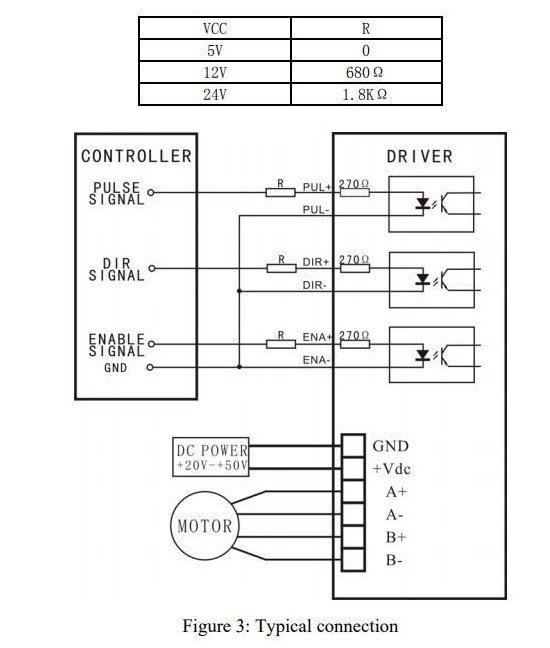
After the output connection is made, you can make the settings by taking into account the resistance amounts and output voltage states required for the connection from the standard connection diagram below.
2) Stepper Motor Driver Standard Connection Diagram

After standard connection settings are made, current settings, microstep settings, power connection and motor connection settings vary depending on the selected driver. In addition, the reasons and solutions for the rotation problems, position and speed problems that occur in the stepper motor driver are included in the driver connection settings datasheet file that you have purchased.
Stepper Motor Driver Jumper Settings
There are 3 sections in the jumper settings of stepper motor drivers. The first section is usually the amperage (current) adjustment section. What needs to be taken into consideration here is that the amperage setting of the driver should be the same as the motor label value in parallel connection, and half of the label value in serial connection. Serial connection is not possible in externally powered stepper motor drivers. The driver becomes extremely tired. Even serial connection
